COUPLINGS
In
engineering applications there arise several cases where two shafts have to be
connected so that power from driving shaft is transmitted to driven shaft
without any change of speed. Such shafts are normally coaxial with slight or no
misalignment and can be connected through devices known as couplings. Permanent
couplings, often referred to as couplings, are the connectors of coaxial shafts
and cannot be disengaged when shafts are running. On the other hand, those
couplings which can be readily engaged or disengaged when driving shaft is
running are termed as clutches. The power is transmitted when a clutch is
engaged and not transmitted when clutch is disengaged. In this unit only
permanent couplings will be considered. Figure 6.10 shows one such coupling
connecting the shaft of an electric motor with the shaft of a worm and worm
wheel reducer.
Several
types of couplings are used in practice. A few are described here.
Muff or
sleeve coupling is shown in Figure 6.11. It is the simplest form of a permanent
coupling, consisting of a steel or cast iron sleeve fitted on the ends of shaft
to be connected. The Keys and Couplings sleeve is connected to the shaft
by means of keys. The length of sleeve can be taken as (3.5 to 4) diameter of
the shaft while the outer diameter of the muff or sleeve, D, is given by
D = 2 d + 13mm
L = 3.5 d
where d is
the diameter of shaft in mm, , the thickness of the muff .
However, the shear stress in the muss must be checked by treating it as a
hollow shat of internal diameter d and external diameter D. The
muff or sleeve coupling has the advantage of simple design and easy
manufacture. However, need of perfect alignment of shafts is apparent and if
not present the connection through a sleeve will induce bending stresses in the
shafts. Yet another disadvantage is that while removing the sleeve must move on
one of the shafts at least over a distance equal to half its length. This
requires the shaft to be longer by this much amount.
The outer diameter of the muff, D, the length of the muff, L, and the bolt diameter db are the dimensions required to be determined for split muff coupling.
The dimensions of the key can be calculated
by strength consideration or selected from standards. Such standards will be
described later in this unit. it will be worthwhile to check compression force
and consequent frictional torque which results from tightening of these bolts.
6.6.1 Flange Coupling
Flange
coupling, as was mentioned earlier is used to connect two strictly coaxial
shafts. One such coupling is shown in Figure. The two flanges are usually made in cast iron. These flanges are
separately keyed to driving and driven shafts.

Fig - Flange Coupling
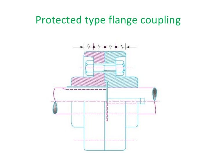
Fig - Protected Type Flange Coupling
Image - Unprotected Type Flange Coupling
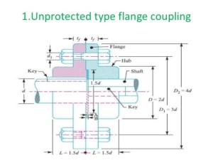
Fig - Unprotected Type Flange Coupling
The two flanges are identical in all respects
except that one has a circular projection and other has a corresponding recess
to make a register. When the two faces of flanges are brought in contact the
projection fits into recess ensuring condition of coaxiality. The flanges are
further connected through bolts placed near the periphery of the flanges. The
faces of flanges are machine finished true right angled to the axis of shafts.
The power may be transmitted by friction between the flange faces or by bolts
in which case bolts will be subjected to shearing stress.
Flange couplings are often employed to
transmit great torque and are largely dependable connections for shafts ranging
in diameter between 18 mm to 200 mm. They are easily designed and manufactured.
Flange coupling normally refers to
unprotected types as shown in Figure. The bolt head and nut, in this case
are fully exposed and may present risk to operators. The bolt heads and nuts
are often protected by providing cover in the flange on them as shown in Figure . This coupling is known as protected flange coupling.
While
designing, the shaft diameter is calculated for transmission of torque,
designated as d. The hub diameter of the flange may be calculated by
treating the hub as hollow shaft but hub diameter D = 2d is often
adopted and is found safe. The thickness of the flange may be calculated by
considering it to be in shear along the circumference where it joins the hub.
However, this thickness, t, is often taken as slightly greater than
diameter of the bolt.
I though this really helped me understand what couplings are and what it's used for. The imagined associated with the different types were really helpful. It was easier to follow along and understand. https://www.cabletecusa.com/online-store/
ReplyDeleteBlog Commenting
ReplyDeleteInformative Blog!!
If you are interested in checking out my blog, I have attached the link below
Blog: https://mechtex.com/blog/reduction-gearheads5
Do like and comment :)
Useful information , introduction of coupling . You might want to check this coupling manufacturers in India
ReplyDelete