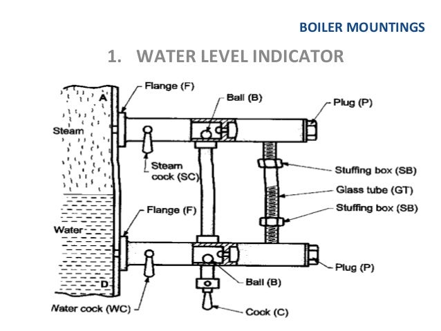
WATER LEVEL INDICATOR
Function:
It is indicates the water level inside the boiler to an observer.
Working:
The
water of the boiler comes into the glass tube through the lower tube and the
steam through the upper tube. The water then stands in the glass tube at the
same level as in the boiler. Two cocks are used to control the passage of
between the boiler and the glass tube while the third cock is in used to
discharge some of the water from inside the boiler to see whether the gauge is
in proper order or not. The glass tube is protected by means of a cover, made
of specially toughened glass, which will prevent any accident that may happen
due to breaking of glass tube. It is used for ordinary boilers.
Nice blog and absolutely outstanding. You can do something much better but i still say this perfect.Keep trying for the best.Mechanical contractor Calgary
ReplyDeleteDigitech Systems is a trusted name in advanced medical imaging solutions, specializing in manufacturing and supplying high-quality Line Frequency X-Ray Machines , High Frequency Fixed X-Ray Machines , and Flat Panel Detectors . As leading X-Ray Bucky Table and Refurbished X-Ray Machine Manufacturers , we are committed to delivering precision, in Line Frequency X-Ray Machine Manufacturers novation, and reliability to healthcare providers. Choose Digitech Systems for dependable imaging technology designed to support accurate diagnostics and improve patient care.
ReplyDelete
ReplyDeleteGreat explanation of the water level indicator's function and working! It's interesting how the glass tube provides such accurate insights into the water level inside the boiler. Keep up the good work on explaining technical concepts clearly.
Your article explains the benefits of CAD and CAM in a simple and practical manner. Well done! Kalyan Panel Chart
ReplyDeleteVery well written. The examples make the concepts easier to visualize and understand. Milan Night Jodi Chart
ReplyDeleteThis post is useful for anyone wanting to explore computer-aided engineering tools. Milan Night Chart
ReplyDelete